
Mercury MR52 connections
As part of your Synergis™ Cloud Link installation, you might need to include a Mercury MR52 interface module.
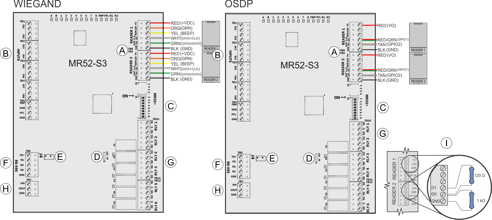
| A | Reader connections | The wire colors in the illustration refer to "pigtail" HID
readers; the information in parentheses refers to "terminal block"
HID readers. Connect the drain wire of the shielded cable to the GND contact of the interface module's reader port. For OSDP daisy-chained readers, do not connect the drain wire to the last reader. |
| B | Inputs | Inputs 1 - 8 can be configured to use End-Of-Line (EOL) resistors, and for normally open or normally closed contacts. |
| C | Address switches | Used to set the device address. For more information on address settings on the Mercury module, refer to the manufacturer's instructions. |
| D | Reader power | 12V = 12 V dc at readers, PT = voltage “passed through” to
readers. Important: For UL294
compliant Synergis™
installations, always install the jumper in the PT
position. |
| E | 2W/4W Select | Install the jumper in 2W position (4W is not supported). |
| F | Line termination | For end-of-line interface modules, install jumper J5 (MR52) or J4 (MR52-S3) for 120-ohm line termination (J6 is not used). |
| G | RS-485 | RS-485 bus connection to other Mercury modules. |
| H | Relay outputs | 6 x Form-C MR52: 5A inductive @28 V dc, 0.6 PF MR52-S3: NO: 5A, NC: 3A, inductive @28 V dc, 0.6 PF |
| I | Power In | Connect + to VIN (observe polarity). Connect - to GND. Use 20 AWG wires minimum. |
| J | Resistors | For OSDP integrations, prevent readers from misinterpreting noise
as data on a non-driven RS-485 line by installing a 1k ohm pull-down
resistor from D0 to GND on both Reader 1 and Reader 2. For wiring distances over 10 meters, install a 120 ohm termination resistor between D0 and D1, as well as between A (-) and B (+) on the RS-485 bus of the last connected reader. To find out whether you need to add a 1K ohm pull-down resistor between D0 and GND, see KBA-78953. |