As part of your Synergis™ Cloud Link installation, you might need to include a
Mercury LP4502 intelligent controller.
Important:
LP controllers include a Micro USB port. This connection is not
to be used if UL/ULC listed access control system compliance is required and is to
be maintained.
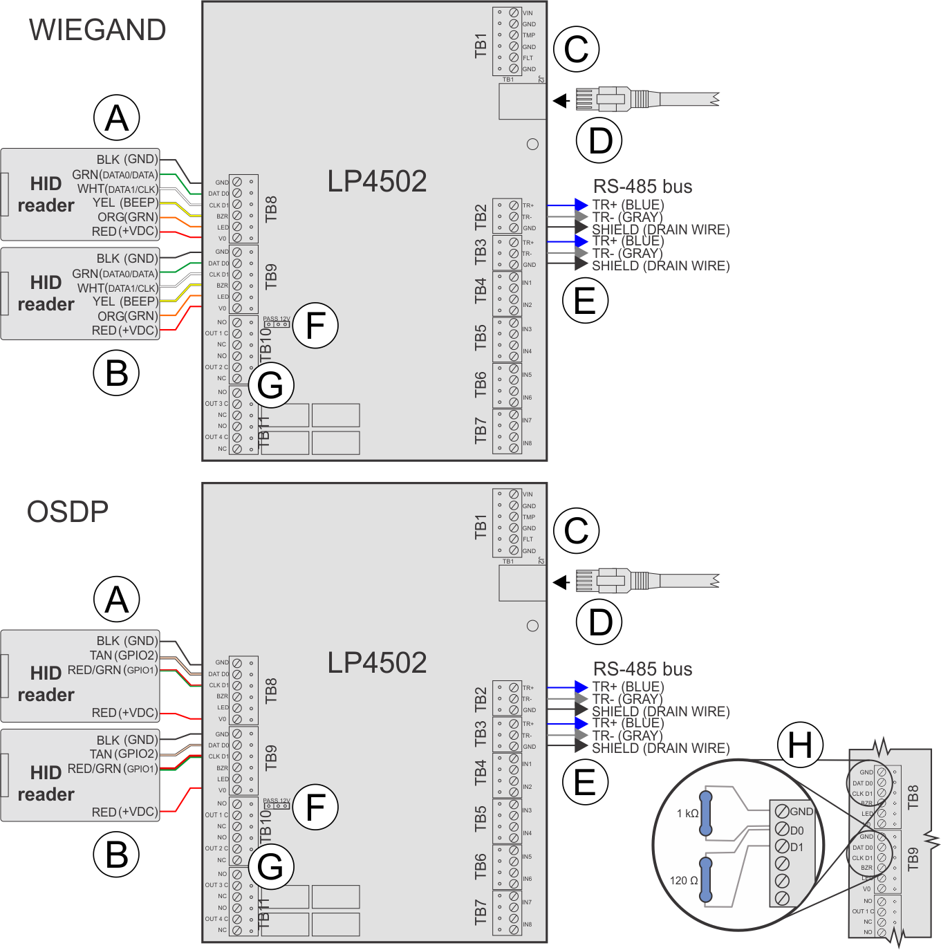
The following diagram demonstrates how to connect the controller.
A
Reader connections
TB8: Door 1 Reader
Note:
The wire colors in the illustration refer
to "pigtail" HID readers; the information in parentheses refers
to "terminal block" HID readers. Connect the drain wire of the
shielded cable to the GND contact of the interface module's
reader port. For OSDP daisy-chained readers, do not connect the
drain wire to the last reader.
B
Reader connections
TB9: Door 2 Reader
Note:
The wire colors in the illustration refer
to "pigtail" HID readers; the information in parentheses refers
to "terminal block" HID readers. Connect the drain wire of the
shielded cable to the GND contact of the interface module's
reader port. For OSDP daisy-chained readers, do not connect the
drain wire to the last reader.
C
Power In
Connect + to VIN (observe polarity). Connect - to GND. Use 20 AWG
wires minimum.
D
Ethernet cable
Connect to the Synergis Cloud Link directly or through the
network infrastructure.
E
RS-485 bus
RS-485 bus connection to other Mercury modules.
F
Reader power
12V = 12 V dc at readers, PASS = voltage “passed through” to
readers.
Important:
For UL294
compliant Synergis™
installations, always install the jumper in the PT
position.
For OSDP integrations, prevent readers from misinterpreting noise
as data on a non-driven RS-485 line by installing a 1k ohm pull-down
resistor from D0 to GND on both TB8 and TB9.
For wiring distances
over 10 meters, install a 120 ohm termination resistor between
D0 and D1, as well as between A (-) and B (+) on the RS-485 bus
of the last connected reader.
To find out whether you need to add a 1K ohm pull-down resistor between D0 and GND, see KBA-78953.