As part of your Synergis™ Cloud Link installation, you might need to include a
Mercury MR50 interface module.
Note:
For UL certified installations, the output from the MR50's K2 relay must not
leave the room of installation and must be shorter than 30.5 m (100 ft.).
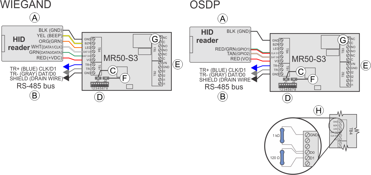
The following diagram demonstrates how to connect the module.
A
Reader connections
Connect one reader.
Note:
The wire colors in the illustration
refer to "pigtail" HID readers; the information in parentheses
refers to "terminal block" HID readers. Connect the drain wire
of the shielded cable to the GND contact of the interface
module's reader port. For OSDP daisy-chained readers, do not
connect the drain wire to the last reader.
B
RS-485
RS-485 bus connection to other Mercury modules.
C
Line termination
For modules at end of line, install jumper J4 (MR50) or J1
(MR50-S3) for 120 ohm line termination.
D
Address jumpers/DIP switches
Used to set the device address. For more information on address
settings on the Mercury module, refer to the manufacturer's
instructions.
E
Power In
Connect + to VIN (observe polarity). Connect - to GND. Use 20 AWG
wires minimum.
F
Tamper input
MR50: Normally closed switch (J3)
MR50-S3: Normally open switch
(J2)
G
Relay outputs
MR50:
Relay 1: 5A inductive, 0.6 PF
Relay 2: 1A inductive, 0.6 PF
MR50-S3:
Relay 1: NO: 5A, NC: 3A inductive, 0.6 PF
Relay 2: 1A inductive, 0.6 PF
H
Resistors
For OSDP integrations, prevent readers from misinterpreting noise
as data on a non-driven RS-485 line by installing a 1k ohm pull-down
resistor from D0 to GND on TB4.
For wiring distances over 10
meters, install a 120 ohm termination resistor between D0 and
D1, as well as between A (-) and B (+) on the RS-485 bus of the
last connected reader.
To find out whether you need to add a 1K ohm pull-down resistor between D0 and GND, see KBA-78953.