RS-485 communication channels
2024-04-22Last updated
The Synergis™ Cloud Link appliance has four on-board RS-485 communication channels for connecting I/O interface modules or card readers.
Consider the following when designing your system:
- The number of modules you can connect to each RS-485 channel depends on the type of interface modules you’re installing.
- You can continue the RS-485 data daisy chain to interface modules outside the enclosure.
- Synergis Cloud Link doesn’t supply power to RS-485 readers. Readers must be powered directly from a separate power source.
RS-485 connector pinout
| Pin | Description |
|---|---|
| + | RS-485 D+ (A) |
| - | RS-485 D- (B) |
| S | Cable shield (GND) |
RS-485 termination DIP switches
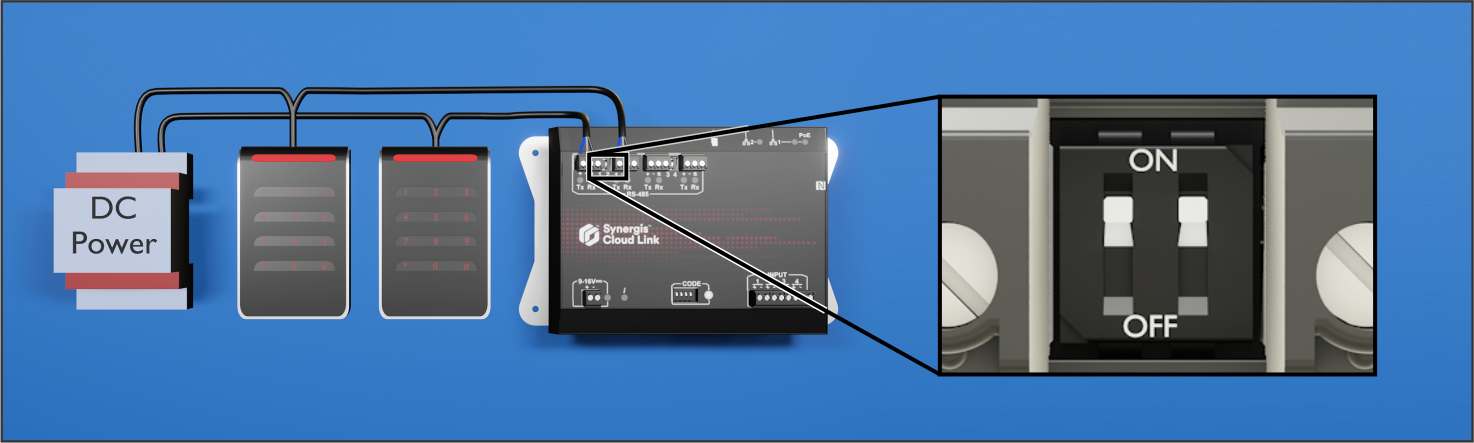
When you start an RS-485 bus from the Synergis Cloud Link appliance for module or OSDP reader communication, you must set the associated termination DIP switch on the appliance to ON.
Note:
Set the termination jumper or add a 120-Ohm resistor on the last connected module
or OSDP reader on the RS-485 bus.
In the following example, card readers are connected to two RS-485 communication channels. The corresponding termination DIP switches are set to ON.